
Автомобильная ЖК-панель для электрического внедорожного
- Категория товара: Auto Meter >>>
- Поставщик (Оптовый магазин): Foshan,Uni,Technology,Co.,Ltd.
Поделиться:
Описание и отзывы
Характеристики

DC-DC Converter
To provide 12V power for dashboard
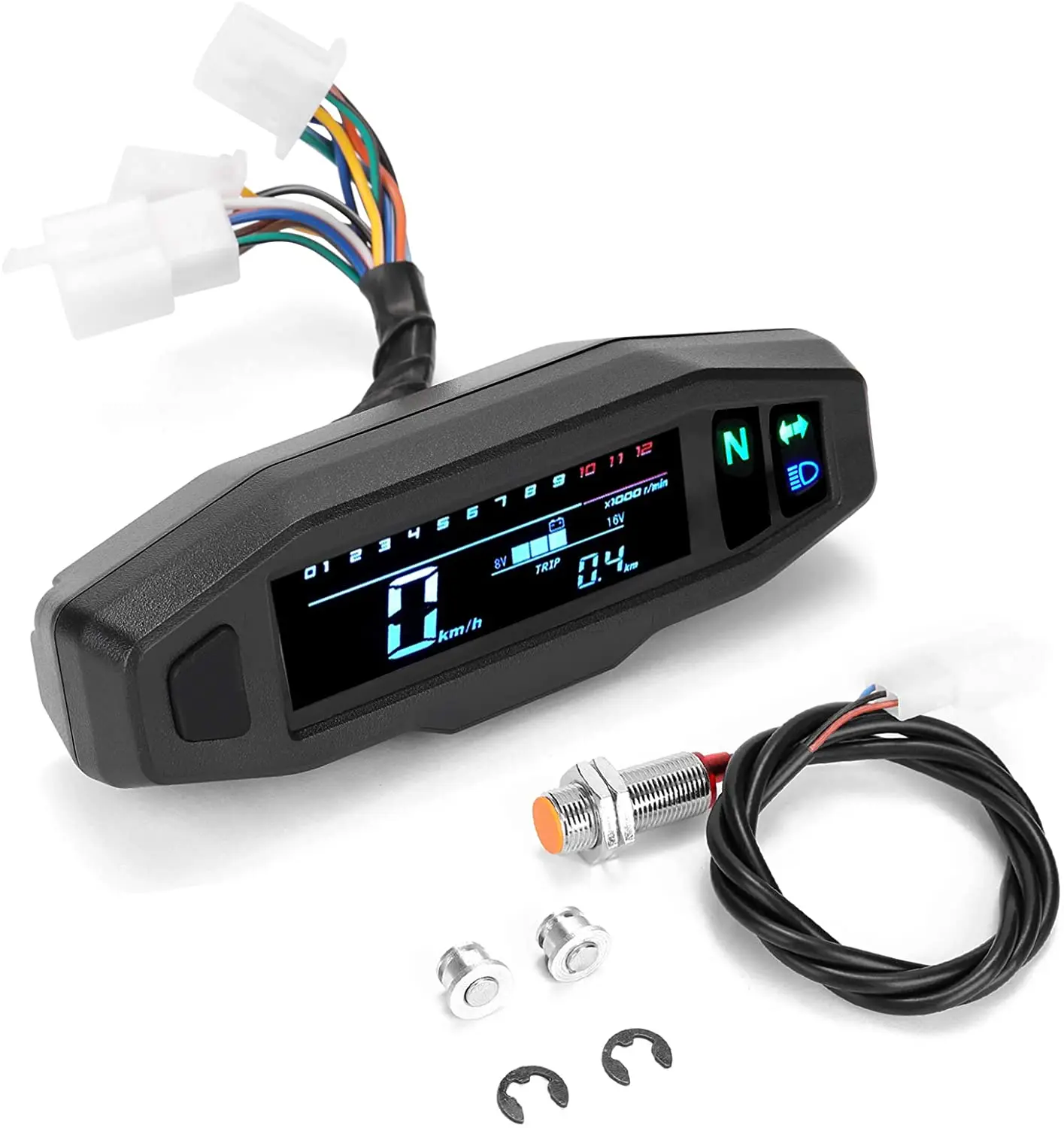
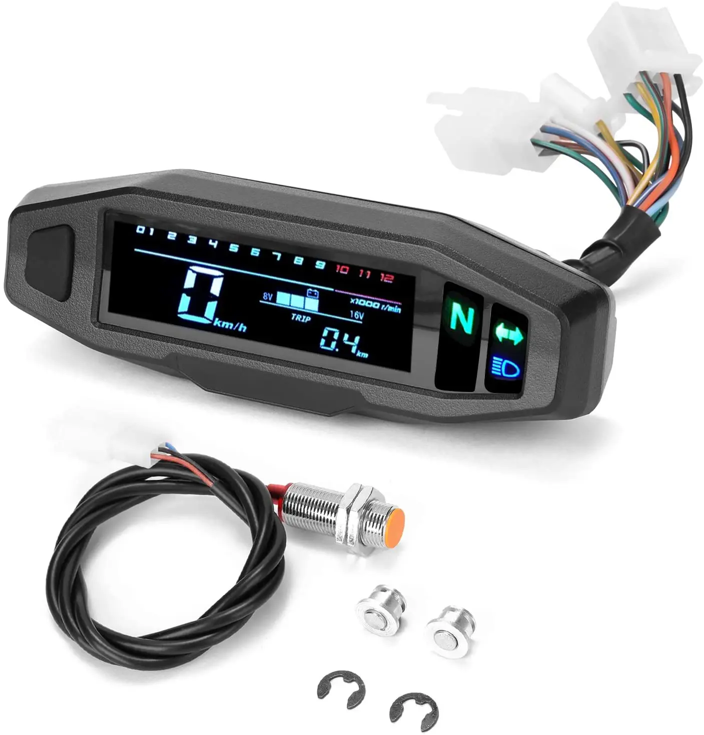
Product Description
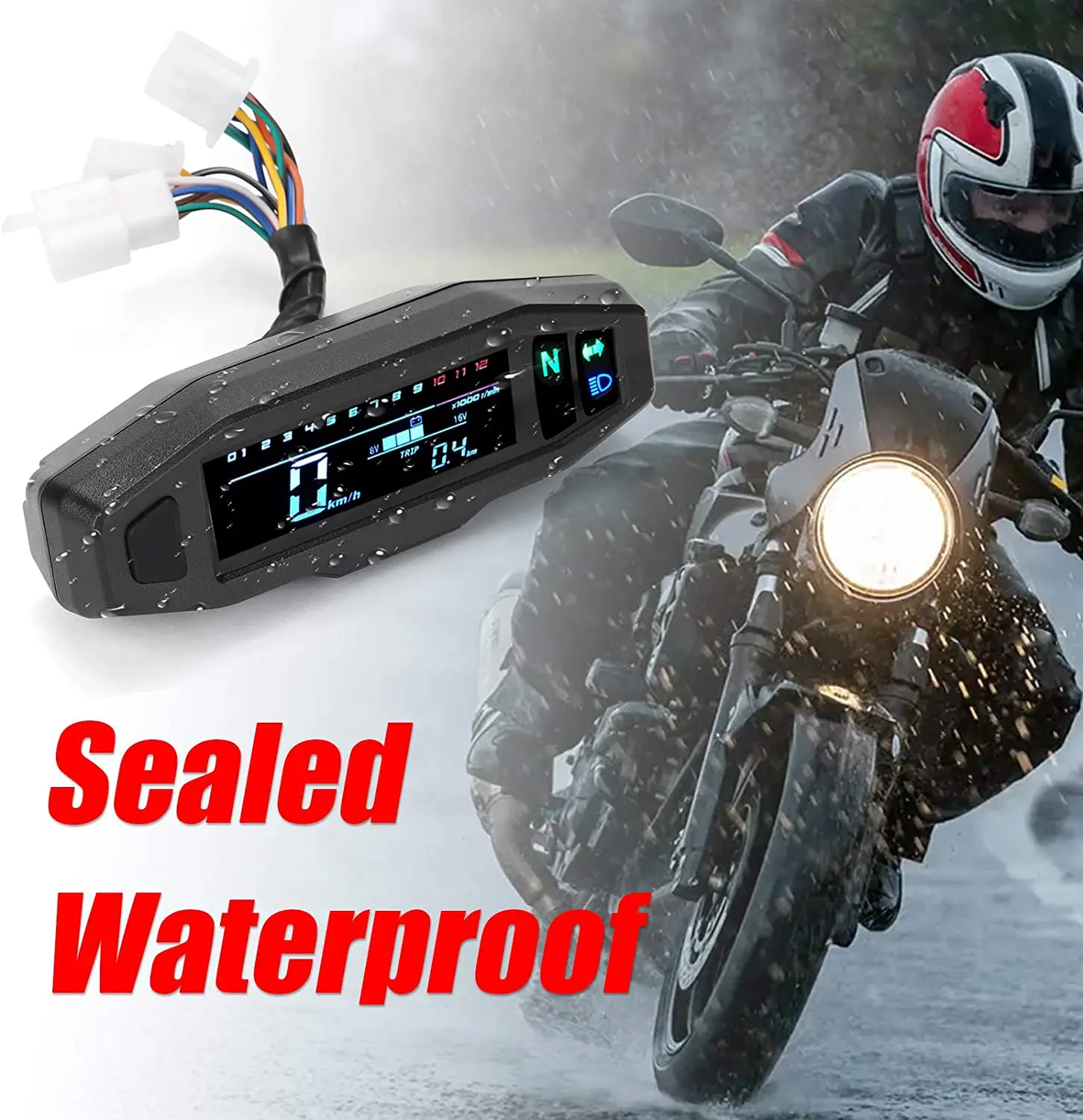
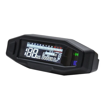
Motorbike Display

Meaning
Enter the setting page.

Meaning
1P: number of engine cylinders; usually it is 1.
E2: number of speed sensor magnets; ususally it is 2.

Meaning
C1903: the circumference of tires; to set according to actual value.
Display Setting Instructions:
Step 1. Enter setting mode:
1. Disconnect all power supply.
2. Press the setting button.
3. Connect power supply.
4. Enter parameter setting page.
Step 2. Set the number of signal:
1. Enter number of signal setting mode; number of signal digit starts flashing.
2. Short press to switch between 1 ~9 signal. Generally, set this parameter to 2.
3. Long press to enter tire circumference setting mode.
Step 3. Set the tire circumference:
1. Enter tire circumference setting mode; matching digit starts flashing.
2. Short press for the top digit to switch between 1 ~ 2, other digits switch between 0~9.
3. 1~3 times long press to enter next digit, for the fourth long press to enter battery setting.
Step 4. Set the number of engine cylinders:
1. Enter number of engine cylinders setting mode; matching digit starts flashing.
2. Short press to switch between 1, 2, 3,4. Generally, set this parameter to 1.
3. Exit the parameter setting mode, and enter normal operation mode.
Step 5. Exit parameter setting mode automatically:
1. If the button has been not pressed for 1 minute in setting mode, it will exit automatically.

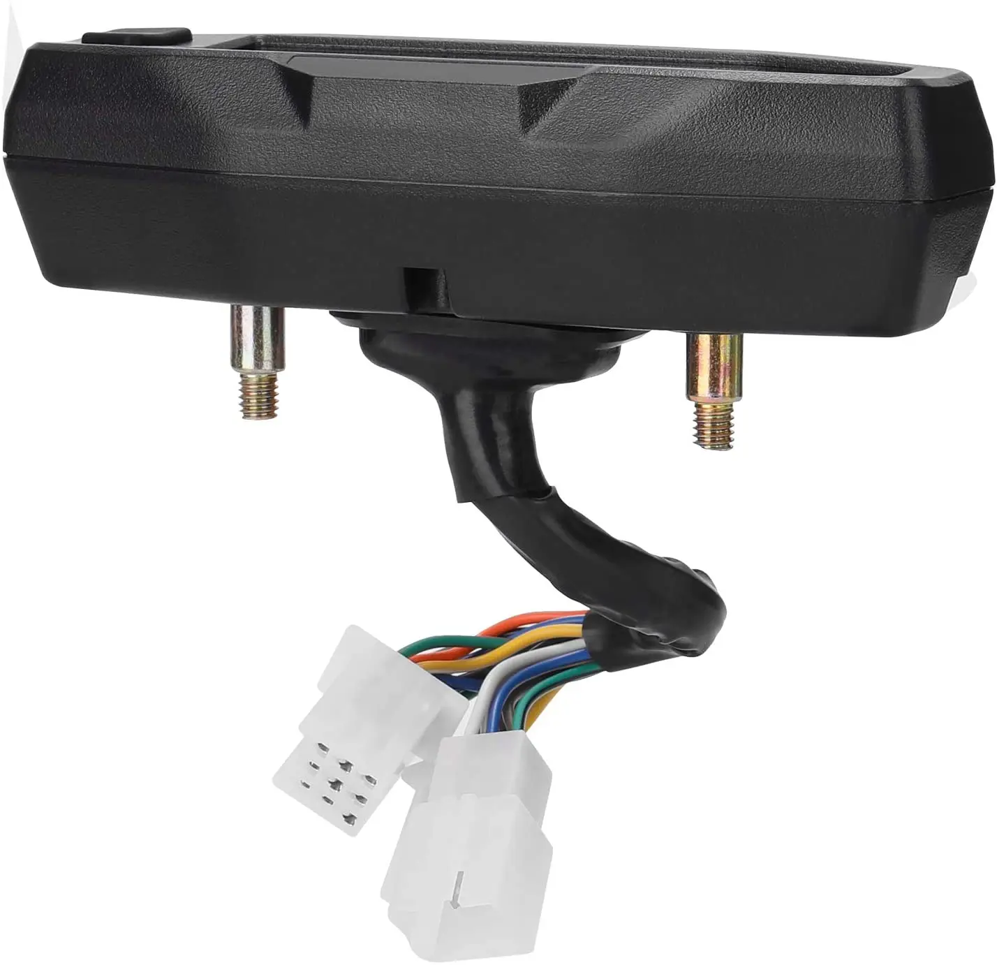
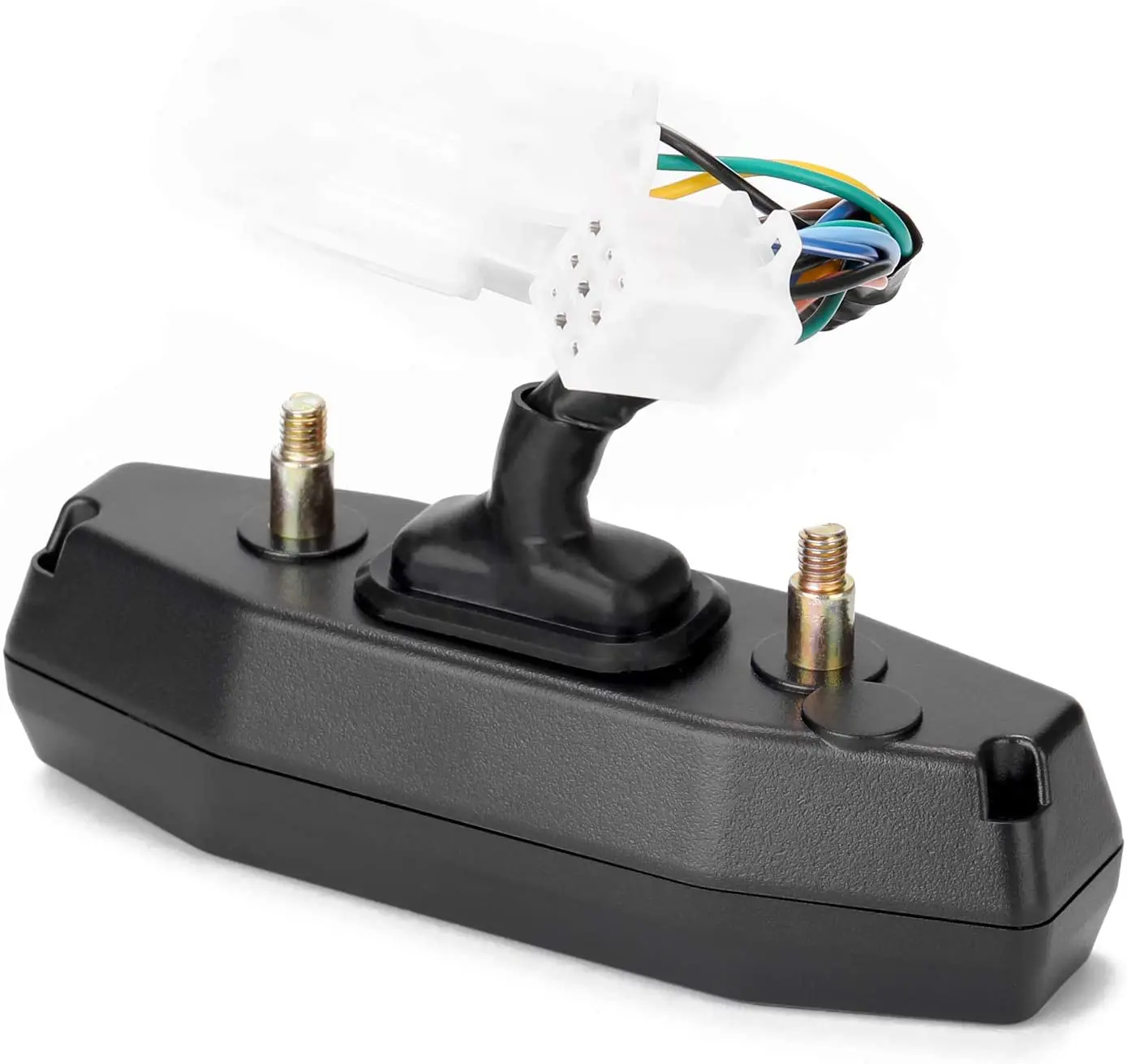
Connectors:
9P Connector:
black: electric door lock (12V positive)
red/black: self-check light (it can be disconnected)
blue/white: speed sensor
orange: left turn light +12V effective
blue: high beam light +12V effective
light blue: right turn light +12V effective
black: electric door lock (12V positive)
red/black: self-check light (it can be disconnected)
blue/white: speed sensor
orange: left turn light +12V effective
blue: high beam light +12V effective
light blue: right turn light +12V effective
yellow/white: battery signal cable
green: negative 12V
green: negative 12V
brown: gear 6, negative control, LCD display
6P Connector:
pink: gear 1, negative control, LCD display
blue/red: gear 2, negative control, LCD display
green/black: gear 3, negative control, LCD display
yellow/red: gear 4, negative control, LCD display
brown/white: gear 5, negative control, LCD display
6P Connector:
pink: gear 1, negative control, LCD display
blue/red: gear 2, negative control, LCD display
green/black: gear 3, negative control, LCD display
yellow/red: gear 4, negative control, LCD display
brown/white: gear 5, negative control, LCD display
red/green: neutral gear
Note: The motor housing needs to be connected to -12v, otherwise the gear signal cannot be displayed.
3P Connector:
yellow: sensor positive pole
green: sensor negative pole
black/white: sensor signal
Note: The motor housing needs to be connected to -12v, otherwise the gear signal cannot be displayed.
3P Connector:
yellow: sensor positive pole
green: sensor negative pole
black/white: sensor signal


