
Настроить 125A 160A реле Smart BMS 96S lifepo4 bms система управления аккумуляторами высокого напряжения RS485 может для хранения солнечной
- Категория товара: Solar Related Products >>>
- Поставщик (Оптовый магазин): Hunan,Gce,Technology,Co.,Ltd.
Поделиться:
Описание и отзывы
Характеристики

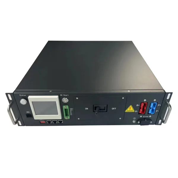
- 307.2V125Amp
Communication protocol:
Rs485, CAN, LAN, dry contact
* 3U standard 19inch case
* Efficient, stable and reliable
* size:W482*H132*D500mm
Accessories
12S-24S BMU(Slave)
12S-24S BMU has 8pcs of tempreture sensors, Fan voltage 48V(17S-24S 12V), voltage detection range 0-5V,12V power
supply,consumption less 20mA, CAN2.0 B communication
supply,consumption less 20mA, CAN2.0 B communication
Wire harness-Signal acquisition wire
18 Pin+20Pin wire, standard length is 600mm,900mm,1200mmtempreture sensor wire: standard length is 600mm,900mm,1200mm
Fan wire: 600mm
Fan wire: 600mm
Wire harness-communication wire
Communication wire is connecting from master BMS to each BMU with cascade connection, the last port is for terminal resistance
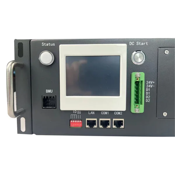
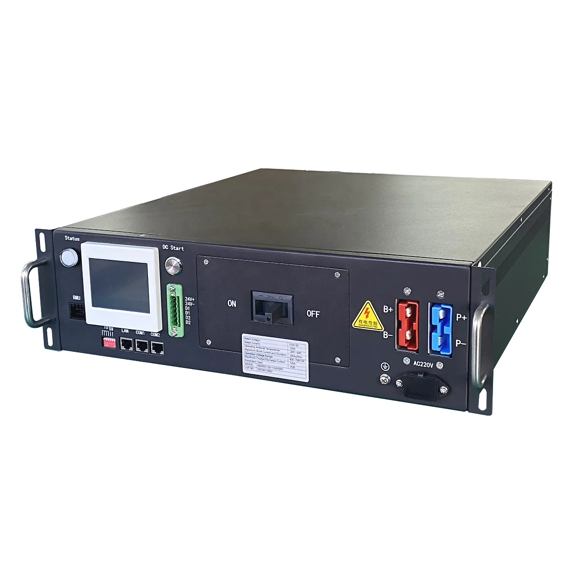
RBMS Interface Description

No. | Name | Explain | matters needing attention |
1 | B+ B- | Power port connected to battery side total positive and total negative | Terminal MPC120 |
2 | P+ P- | Power port connected to charging equipment (UPS) or DC bus | Terminal MPC120 |
3 | AC 220V | The municipal power supply signal input port must be taken from the ups output side | When the Municipal power is on, BMS starts up; Municipal power off, BMS Shutdown (ensure that BMS and mains power are switched on and off synchronously to save BMS's self consumption of battery) |
4 | ON OFF | On: the circuit breaker is closed; Off: the circuit breaker is disconnected | When the handle of the circuit breaker is in the tripping state in the middle position, it needs to be turned to Off before it can be closed. |
5 | D1 D1 D2 D2 | Two dry contact output reserved | No charge, no discharge, dry contact output |
6 | DC Start | DC start button: start RBMS system by taking power from the battery side. | The system is connected to the battery. After the circuit breaker is closed, press and wait for the light to light up, indicating that the system is powered on. |
7 | Status | System status indicator | System normal: the green light is always on System alarm: the yellow light is always on Self test failure and protection status: the red light is always on Charging: the green light flashes Discharge: red light flashing Self checking: red and green flashing alternately Pre-charging: yellow flashing |
8 | 1 2 4 8 | ID allocation: when multiple RBMs are used in parallel, the ID is allocated by setting the dial switch. You must start with 1 | The dial switch has 4 bits in total and supports up to 15 RBMs Parallel machine 1 ON: ID+1 2 ON: ID+2 3 ON: ID+4 4 ON: ID+8 |
9 | LAN | RBMS upper computer system software can be connected to PC through network cable | The network cable standard is CAT5 or above, and can be connected by cross line or straight line. The line sequence can be according to the standard tia-586A or tia-568B |
10 | CAN-R 485-R | Setting description of terminal matching resistance during can and 485 communication: (120R), on is effective | For parallel application, only the last one needs to be set; Single machine should be used flexibly according to the site conditions (interference, communication distance, etc.) |
11 | COM1 COM2 | RBMs external communication port: In parallel application: communicate with SBMS In stand-alone application: communicate with UPS / PCS external equipment | The randomly configured twisted pair shielded harness must be used. See the harness label for the definition of wire sequence |
12 | GND 24V | For supplying power to SBMS | |
13 | BMU | Communication interface with BMU | communication with BMU level |
14 | RBMS cabinet ground point | It must be reliably grounded and the grounding resistance is less than 1 ohm |
Specification
Basic parameters | Max Current | 125A |
Max voltage | 350V.600V(Optional) | |
Power consumption | ≤15W | |
Current sampling accuracy | 1%FSR | |
Insulation withstand voltage | 2800VDC <1mA 1min | |
Protection level | IP20 | |
Dimension(W*H*D) | 482*132*500(mm) | |
Net Weight | ~15Kg | |
Communication Port | Communication port with BMU | CAN |
Communication port with UPS | RS485/CAN | |
Communication port with SBMS | RS485/CAN | |
Communication with monitoring software | Ethernet | |
Basic Function | Battery charge&discharge Management | available |
Battery Temperature Management | available | |
IAP Upgrade | available | |
System protection parameter setting | available | |
Short circuit protection | available(20KA 20ms) | |
Pre-charge function | available | |
Parallel circulation control | available | |
Event record | Available 5000pieces | |
DC power Start | available (battery powered, municipal power as on / off signal) | |
Functions Optional | Insulation detection | Applicable to system voltage ≧300V |
HMI display | 3.5 inches display (embedded inside the cabinet) | |
Stand-alone or parallel function | Set up before leaving the factory | |
Dry contact | Maximum 2 dry contact outputs (optional) | |
Others | Appearance, Color | RAL9005 Black sand grain |
Installation method | Suitable for standard 19- inch cabinet installation | |
Incoming and outgoing line mode | Front side in and front side out. | |
Operating ambient temperature | -20℃~60℃ | |
Operating ambient humidity | 5%~75%RH | |
Comply with National standards | GB/T 16935.1 GB/T 17626.2 GB/T 17626.5 | |
Safety Certification | Comply with CE certification standards |


Product Feature
1 | Advanced Battery Management System --- The highly integrated battery management system enables seamless monitoring. |
2 | perfect self-test and operational status detection, with HMI display, system operation information at a glance. |
3 | perfect and reliable system control and protection strategies to fully protect the battery safety, extend the life of the battery escort. |
4 | Modular design, configurable, scalable --- flexible combination of multiple energy storage unit can be expanded to a larger energy storage system, the maximum can support 272 (lead-carbon battery 400) battery series. |
5 | Rich communication interface --- multiple RS485, CAN, Ethernet, dry contact input and output interfaces, support for most of the market with PCS, monitoring server communication. |
6 | Flexible communication interface protocol --- The company comes with the company's communication protocol, but also according to customer needs to adapt to PCS of different manufacturers. |
7 | Capacity is large --- Built-in large-capacity memory chips can store a large number of key operational data, but also can install an SD card for offline access. |
8 | PCS has a protocol control function, the choice of circuit breaker version . |
9 | PCS without protocol control function, the choice of contactor + breaker version |
10 | Automatic circulation control and automatic parallel machine \\ offline control can easily realize the parallel connection of battery packs. |
Company Profile


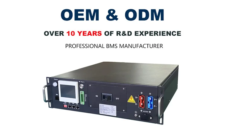
Hunan Group Control Energy Technology Co., Ltd.(GCE) is a high-tech company specializing in the research and development of BMS and lithium battery peripheral equipment. The high-performance intelligent lithium battery management system produced by our company adopts the international leading technology, which greatly improves the battery management efficiency and prolongs the service life of lithium battery. The advanced BMS control strategy avoids the difficulties and instability faced by most competitors for our BMS.
4S to 24s low voltage software BMS has a wide range of uses, rich product interfaces, strong scalability and secondary development compatibility; 30s to 75s BMS adopts master-slave integrated design and relay solution to meet the lithium battery demand of multiple strings of small capacity batteries. Greatly reduce the use cost of users; 60s-270s adopts master-slave three-level architecture, which can meet the series and parallel requirements of high-capacity single lithium batteries within 1000V.
Certification

Packing&Shipping

FAQ
1. Are you a manufacturer or simply a trading company?
We are a manufacturer, and we sincerely welcome you to visit our factory.
We are a manufacturer, and we sincerely welcome you to visit our factory.
2. Can I get some samples?
Yes, a sample order is available for quality checking and market testing.
3. What kind of cells are applicable to this Battery Management System?
LFP, NMC, LTO
4. How about the delivery time?
The lead-time usually takes about 15 to 20 working days accordingly to the specification of your order and quantity.
5.What are your terms of payment?
Advanced T/T is the main payment term, and other payment terms are negotiable. Please contact us, we’ll discuss the details.
6. What are your warranty terms?
We offer a 3-year warranty for RBMS,1-year warranty for PCB.
7. Can you produce BMS with customization requirements?
Yes, based on the order quantity, we can make some small adjustments.
8. How does your factory do regarding quality control?
Quality always comes first. All our products go through strict quality control processes from incoming material to the assembling process. Each product will be tested before packing & shipping.
9. What Trade Terms are available?
No limitation on the trade terms. We normally do EXW for orders amounts smaller than 20000USD, and FOB for the rest ones. Moreover,we can send BMS via DHL&UPS&FEDEX quickly and easily.
10. Is your BMS easy and convenient to install&test?
This is our the 4th generation high voltage bms.It's an overall bms solution, that is to say, you don't need professional
technology to install our high-voltage BMS to form a complete battery system.
11.What benefits do customers get?
Our high voltage BMS has complete battery charge and discharge control logic and balance function between batteries. We can also set various parameters of the system according to the actual needs of customers to ensure the stability, reliability and efficient performance of the system.
12:How to Contact with you?
You can contact with Cara for quotation.Her whatsapp&Skype:+8617321496453, Email:cara@hngce.com
Похожие товары


