


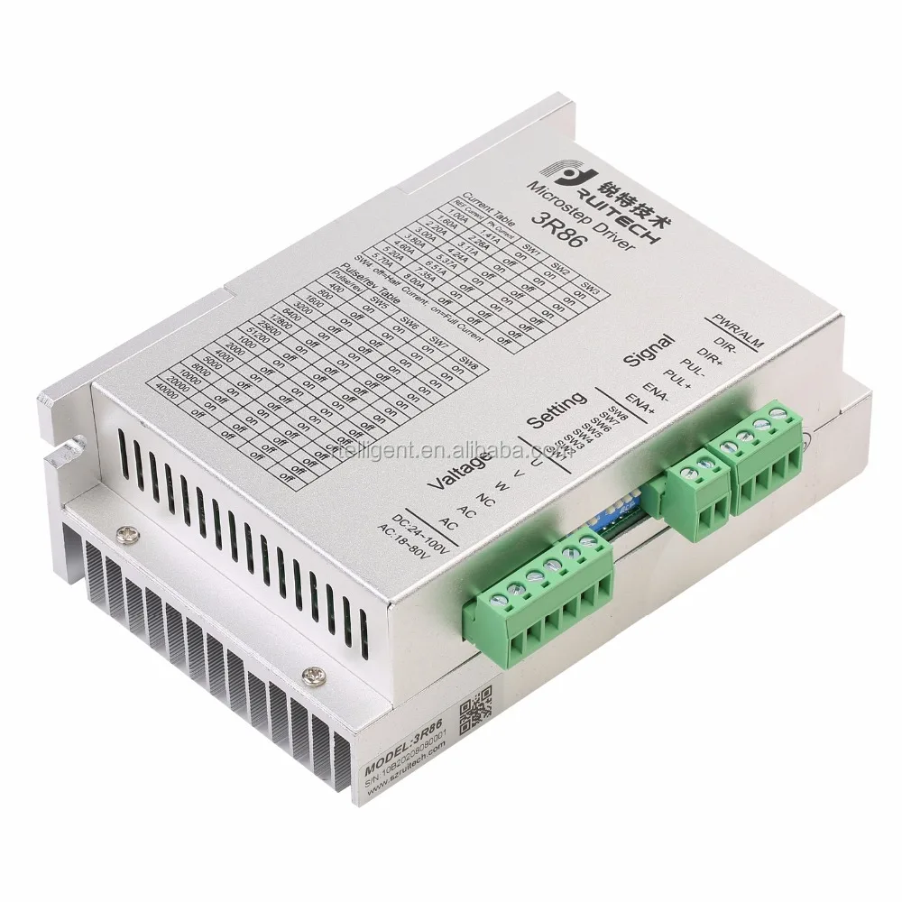
Безуходный 3-х фазный 3R86 Драйвер шагового двигателя для Nema23
- Категория товара: >>>
- Поставщик (Оптовый магазин): Shenzhen,Rtelligent,Mechanical,Electrical,Technology,Co.,Ltd.
Поделиться:
Описание и отзывы
Характеристики
Product Description
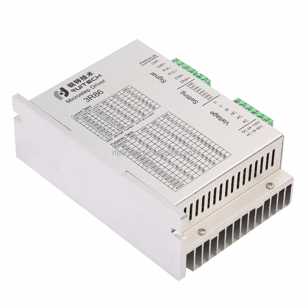
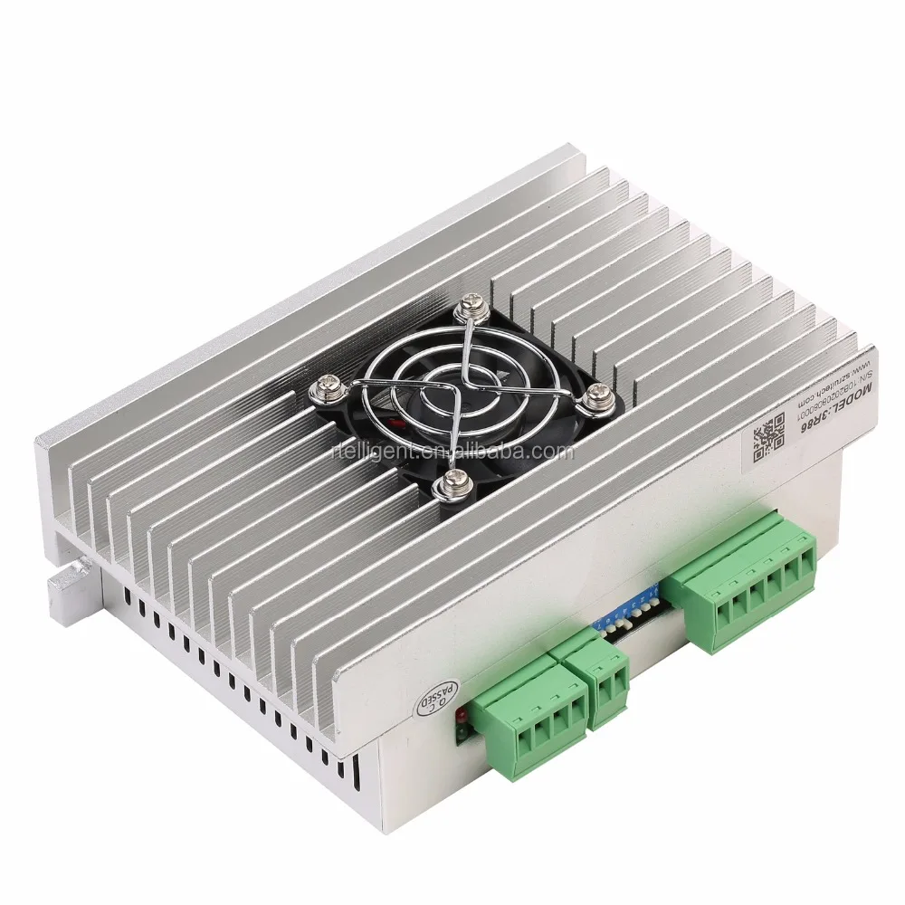
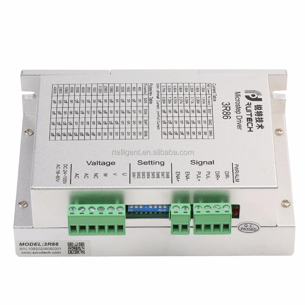
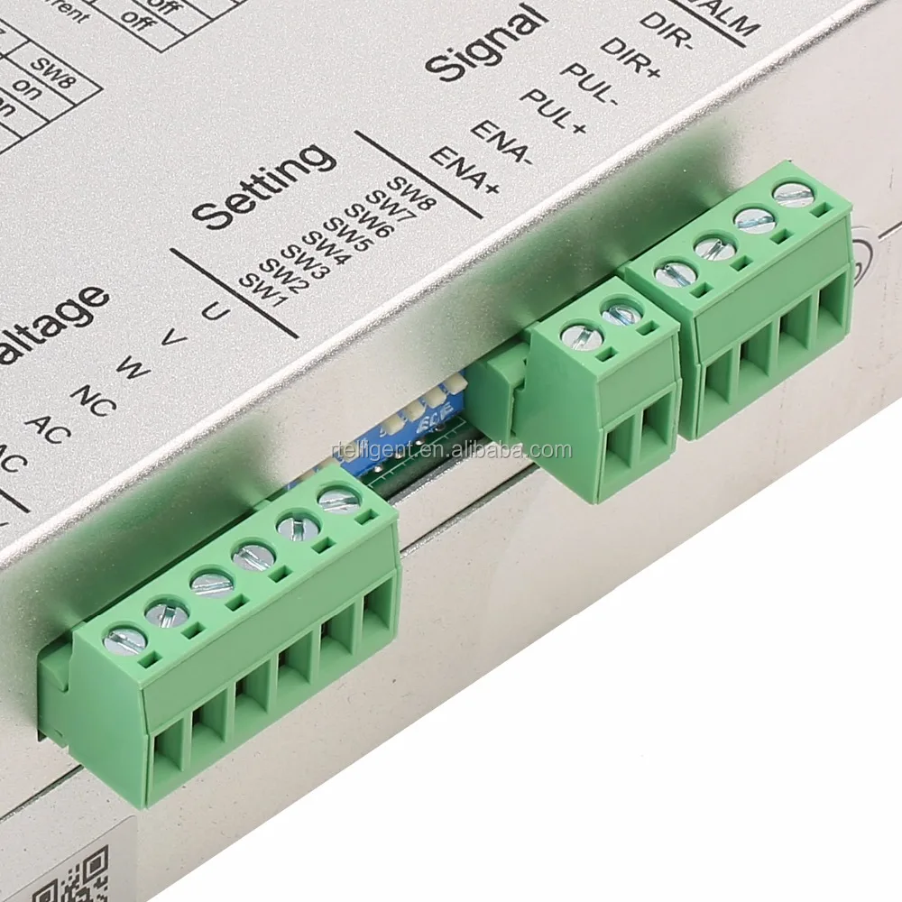
3-phase 3R86 Stepper Motor Driver for Nema23,34 motor
The 3R86 digital 3-phase stepper drive is based on TI’s 32-bit DSP platform and integrated with the micro-stepping technology and the patented three-phase demodulation algorithm. With the features of low noise, low vibration, low heating and high-speed high torque output, it allows the three-phase stepper motor itself to deliver full performance benefits.
Detailed Images
| \t | |
| \t | \t |
| \t | \t |
| \t | \t |
| \t | \t |
| \t | \t |
| \t | \t |
| \t | \t |
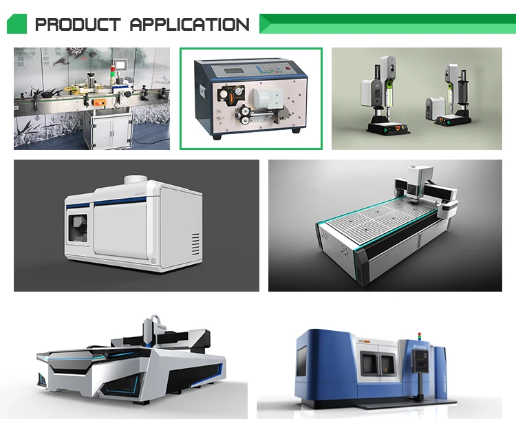
Application
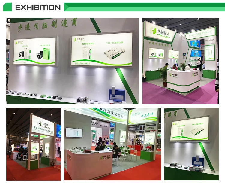
About Us
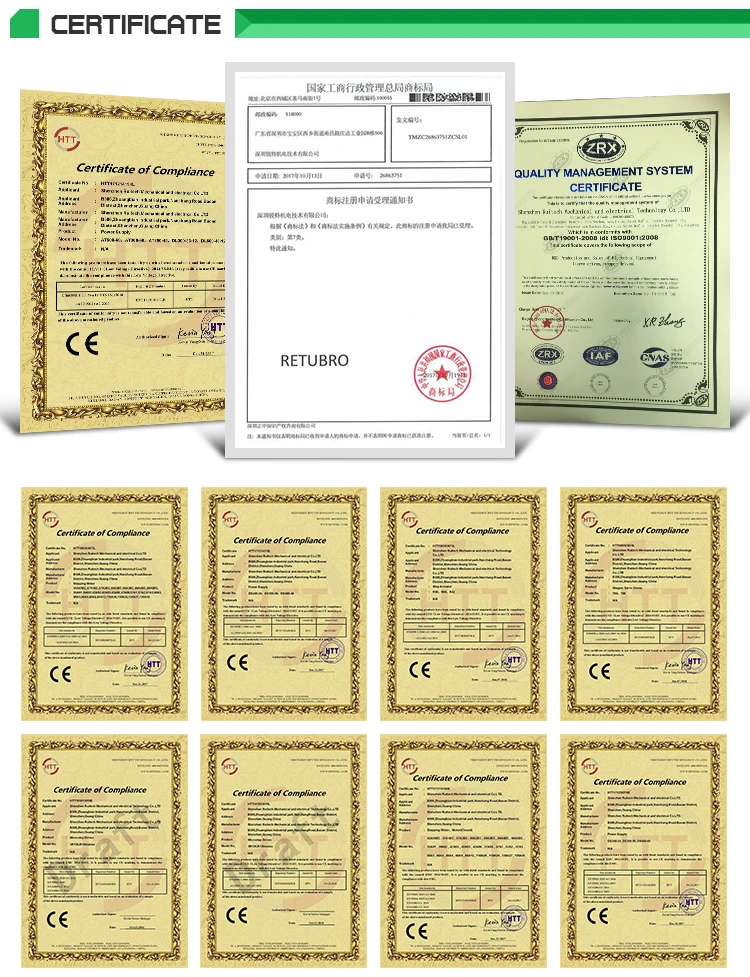
Certifications
RFQ
Contact Ways
Packing & Delivery
12PCS/CARTON
Похожие товары


Сервопривод и Сервопривод переменного тока
US $230.00-$550.00


Новый Серводвигатель HFC 750 Вт
US $289.20
